
Across the Western Ghats—from the steep tea scarps of Meppadi and Chooralmala in Wayanad to the mist-saturated gaps of Chinnakanal and Devikulam in Munnar, and the sheer grass slopes of Vagamon and Peerumade—the most dramatic, high-tariff resort locations are almost always on steep terrain.
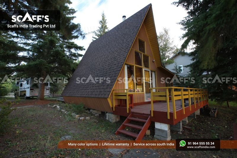
Guests pay ₹12,000 to ₹18,000 per night specifically for vertigo-inducing cliff views, suspended valley decks, and morning mist rising directly beneath their balconies.
Yet for resort developers and plantation owners, steep slopes carry an acute operational and psychological anxiety: landslide vulnerability and catastrophic slope failure.
Between June and September, the Southwest Monsoon unleashes over 4,000 mm of concentrated downpours across Kerala’s mountain spine. In conventional construction, steep hillside building routinely triggers disaster:
The Excavation Cut-Slope Disaster: Standard contractors bring heavy hydraulic excavators to carve flat, terraced “benches” into 30° hillsides. Cutting the natural slope toe removes lateral support from the soil layers above, creating an unstable, vertical slip face that shears away during heavy rains.
The “Surcharge Weight” Collapse: Pouring 120 to 180 metric tons of wet concrete slabs, brick walls, and concrete retaining barriers adds massive downward dead load to the upper hillside. When rain saturates the soil, this excessive mass drives downward sliding along subterranean shear planes.
Aquifer Damming & Hydrostatic Pressure: Heavy stone retaining walls built without deep hydrologic drainage act as subterranean dams. Trapped groundwater pools behind the wall, building extreme hydrostatic pressure until the entire barrier bursts, taking the villa down the slope.
Regulatory Red Tape: Because of recent highland landslides, the District Disaster Management Authority (DDMA) and local Grama Panchayats strictly scrutinize or reject masonry resort proposals on slopes exceeding 20°.
At Scaffs India, we eliminate the root causes of slope failure through non-invasive geotechnical engineering. Instead of altering the mountain with heavy cut-and-fill operations, we anchor lightweight structural steel chalets above the natural grade on deep-drilled bedrock micro-stilts. Explore our turn-key A-frame resort solutions to see how our engineering ensures stability on the most demanding hillside topography.
1. Geotechnical Slope Mechanics: Surcharge Mass vs. Shear Strength
Slope stability is governed by the Coulomb-Terzaghi shear strength equation:
Where $\tau_f$ is soil shear strength, $c’$ is effective cohesion, $\sigma_n$ is normal stress (gravitational weight), $u$ is pore-water pressure, and $\phi’$ is the internal friction angle.
When continuous monsoon rains drench the mountains:
Pore-Water Pressure ($u$) Spikes: Water fills the microscopic voids between laterite soil particles, pushing them apart and reducing friction ($\tan \phi’$) to near zero.
Soil Cohesion ($c’$) Drops: Saturated laterite soil loses internal binding strength, transitioning from a solid state to a liquid-like slurry (liquefaction).
The Surcharge Catalyst: If a heavy 150-ton masonry building rests on that saturated layer, the downward driving force easily overwhelms the compromised shear strength, triggering a rotational or planar landslide.
[ CONVENTIONAL MASONRY FAILURE VS. SCAFFS INDIA STILT EQUILIBRIUM ]

  CONVENTIONAL CIVIL APPROACH (Massive Slope Failure Risk):
  Excavator cuts toe ──► 150-Ton Heavy Masonry Surcharge ──► Hydrostatic Dam
  ═════════════════════════════════════════════════════════════════════════►
  Soil shears at saturated interface; retaining wall bursts; slope collapses

  SCAFFS INDIA GEOTECHNICAL STILT CHASSIS (Factor of Safety FoS >= 1.8):
  Natural Grade Preserved ──► 12-Ton Lightweight Steel ──► Zero Aquifer Interruption
  ═════════════════════════════════════════════════════════════════════════►
  Loads routed via point stilts into solid granite bedrock 2.0 m deep; zero slip
By engineering our 550 sq ft luxury chalets with an total structural dry mass of only 12 to 14 metric tons (less than one-tenth the weight of a concrete villa), we keep downward gravity loads within the natural bearing capacity of the hillside.
2. Deep-Drilled Bedrock Anchoring: The Micro-Stilt Foundation
Rather than excavating massive continuous strip footings or pouring broad concrete slabs that disrupt the slope, Scaffs India’s foundation touches the earth at only 4 to 6 isolated point locations:
[ CORE-DRILLED BEDROCK MICRO-STILT FOUNDATION SCHEMATIC ]

  ELEVATED LIVING CHASSIS (Structural Steel ISMB / RHS Girder)
  ════════════════════════════════════════════════════════════════════════
         │                                                 │
  [ M30 RCC FRONT STILT PILLAR ]                    [ M30 REAR STUB PILLAR ]
  (Carries Compressive Gravity Loads)               (Resists Overturning Tension)
         │                                                 │
  ───────┴─────────────────────────────────────────────────┴─────────────
  NATURAL TOPSOIL & WEATHERED LATERITE HORIZON (Unexcavated 30° Slope)
  ────────────────────────────────────────────────────────────────────────
  UNWEATHERED BASAL GRANITE / CHARNOCKITE BEDROCK STRATA
  ┌─────────────────────────────┐                   ┌────────────────────┐
  │ 32 mm CORE-DRILLED BOREHOLE │                   │ 32 mm CORE BOREHOLE│
  │                             │                   │                    │
  │ ├── High-Tensile Grade 8.8  │                   │ ├── Grade 8.8 Rod  │
  │ │   Galvanized Threaded Rod │                   │ │   (Epoxy Grouted)│
  │ └── Hilti HIT-RE 500 V3     │                   │ └── 2.0 m Embedment│
  │     Structural Epoxy Grout  │                   │                    │
  │                             │                   │                    │
  │ ANCHOR PULL-OUT CAPACITY:   │                   │ TENSION CAPACITY:  │
  │ >= 180 kN PER ANCHOR PIN    │                   │ >= 180 kN          │
  └─────────────────────────────┘                   └────────────────────┘
Core-Drilled Rock Sockets: Using portable diamond core-drilling rigs, our crews drill 32 mm to 40 mm diameter boreholes 1.5 to 2.5 meters deep directly into solid granite or charnockite bedrock.
Chemical Epoxy Injection Anchoring: We install high-tensile Grade 8.8 hot-dip galvanized threaded anchor rods set with pure structural epoxy injection mortars (Hilti HIT-RE 500 V3). Each anchor pin develops a pull-out tensile capacity exceeding 180 kN (18.3 metric tons), locking the base column mechanically into the bedrock formation.
Isolated M30 Stub Columns: Above the rock socket, isolated reinforced concrete stub pillars ($500 \times 500\text{ mm}$ or $600 \times 600\text{ mm}$) are cast using M30-grade sulfate-resistant concrete with corrosion-resistant TMT rebar cages. These columns elevate the steel chassis completely above the ground plane.
Shear Keys for Lateral Sliding Resistance: The base plates feature recessed mechanical steel shear lugs extending downward into the concrete pillar head, providing direct physical resistance against lateral sliding forces generated by seismic activity or mountain wind shear. Review our wind-shear engineering in high-wind engineering for mountain storms.
3. Slope Hydrology: Preserving Subterranean Drainage Paths
The primary physical trigger of mountain landslides is water accumulation. When natural subterranean drainage paths are blocked, water pressure accumulates until the ground gives way:
The Elevated Chassis Clearance: Our chalets hover 1.2 to 3.5 meters above the natural ground surface. Surface sheet runoff from monsoon downpours flows unobstructed beneath the building, following the mountain’s natural gullies without pooling or washing out foundations.
Zero Disruption to Sub-Surface Aquifers: Traditional deep foundation cuts sever subterranean water veins, forcing underground streams to find new paths through loose backfill. Because our micro-piles occupy less than 1.5 sq meters of total subterranean contact area across the entire site, deep groundwater aquifers remain undisturbed.
Integrated Deep French Drains: Up-slope from each cottage cluster, we install shallow subterranean interceptor trenches (French drains) wrapped in non-woven geotextile filter fabric and backfilled with clean 40 mm crushed granite aggregate. These drains capture high-velocity subsurface sheet flows and route them safely around the structural footprint into natural rocky discharge channels. Learn how this pairs with water catchment in off-grid utility engineering.
4. Factor of Safety (FoS): Geotechnical Performance Comparison
In civil slope stability analysis, the Factor of Safety ($\text{FoS}$) expresses the ratio of resisting forces to driving forces ($\text{FoS} = \text{Resisting Forces} / \text{Driving Forces}$). An $\text{FoS} < 1.0$ indicates immediate structural failure, while Indian Standard codes (IS 14458) mandate an $\text{FoS} \ge 1.5$ for permanent hillside infrastructure:
| Geotechnical Parameter | Conventional Masonry Villa on Sloping Terrain | Scaffs India Elevated Micro-Stilt A-Frame |
| Site Excavation Depth | Deep bench cut (2.5 m to 5.0 m vertical cut face) | Zero excavation; 100% surface soil integrity |
| Foundation Dead Mass | 120 to 180 Metric Tons (Massive downward surcharge) | 12 to 14 Metric Tons (Ultra-lightweight structural load) |
| Retaining Wall Dependency | Requires 3 to 6-meter-tall rubble/concrete walls | Zero retaining walls required |
| Subsurface Water Impact | Traps hydrostatic pressure behind masonry | Zero obstruction; natural drainage flows freely |
| Foundation Anchoring | Shallow footings resting on unstable topsoil/laterite | Bedrock-grouted chemical anchors (1.5 m – 2.5 m deep) |
| Slope Factor of Safety ($\text{FoS}$) | 1.1 to 1.3 (High risk of failure during monsoons) | 1.85 to 2.20 (Certified high-stability threshold) |
| Disaster Authority Clearance | Flagged/delayed by DDMA in high-hazard zones | Smoothly cleared under eco-tourism stilt exemptions |
By achieving a Factor of Safety above 1.85, our engineering provides the geotechnical documentation required to secure building permits under the Kerala Panchayat Building Rules (KPBR), even in hill taluks designated as landslide-sensitive zones. Review our permitting pathways in navigating KPBR permits and eco-zoning.
5. Biological Slope Stabilization: The Vetiver Root Reinforcement Matrix
Engineering stabilization works best when paired with nature’s own soil reinforcement:
[ BIOLOGICAL REINFORCEMENT & DEEP ROOT MATRIX ]

  SURFACE TOPOGRAPHY (30° Slope Around Chalet Stilts)
  ─────────────────────────────────────────────────────────────
  ▲  [ GROUND TIER: VETIVER GRASS (Chrysopogon zizanioides) ]
  │  • Planted in dense contour hedgerows 1.0 m apart
  │  • Massive tensile strength (75 MPa: equivalent to mild steel)
  │  • Root network penetrates 3.0 m to 4.0 m straight down
  │
  ▼  [ SUB-SURFACE SOIL KNITTING ]
  ═════════════════════════════════════════════════════════════
  Roots lock topsoil layers into dense shear-resistant web;
  Prevents surface sheet erosion & mud slips during 100 mm/hr downpours
Living Soil Nails: Around each stilted chalet, we plant contour hedgerows of Vetiver grass (Chrysopogon zizanioides). Unlike standard trees whose heavy surface branches can blow over in high winds and loosen soil, vetiver roots grow straight down up to 3.5 to 4.0 meters deep, forming a subterranean root matrix.
75 MPa Root Tensile Strength: Laboratory testing confirms that mature vetiver roots exhibit an average tensile strength of 75 MPa—comparable to structural steel reinforcement. These biological “soil nails” knit the upper laterite soil layers directly to underlying weathered rock, preventing surface mud-slips during heavy cloudbursts.
Preserving Existing Tree Root Canopies: Our structural frames are positioned to work around mature plantation shade trees (silver oaks, jackfruit, wild cedar). Their root networks are left completely undisturbed, keeping the natural hillside structural integrity intact. Learn more about crop protection in monetizing hillside acreage.
6. The Developer’s Bottom Line: Cost Certainty vs. The Retaining Wall Black Hole
Building on steep terrain with conventional civil methods is a financial gamble. For a standard 550 sq ft cottage, constructing a 4-meter-tall reinforced rubble retaining wall across a 15-meter slope width routinely costs ₹6,00,000 to ₹10,00,000 in stone, cement, manual labor, and backfill gravel before room construction even begins.
With Scaffs India’s elevated steel-stilt system:
The Retaining Wall Budget Drops to Zero: The structure adapts to the hill slope via varying column heights, eliminating the need to build earth-retention walls.
Zero Excavation Disposal Costs: You avoid paying ₹1,50,000 to ₹3,00,000 to haul hundreds of tons of excavated hill soil off-site over narrow mountain roads.
Faster Project Timelines: While a heavy retaining wall requires 6 to 8 weeks to dig, lay, and cure, our core-drilled bedrock anchors and stilt columns are drilled, grouted, and ready for chassis erection in just 5 to 7 days. Review full financial modeling in our turnkey cost breakdown and BOQ analysis.
Turnkey Hillside Engineering with Scaffs India
Whether you are planning an exclusive honeymoon chalet overlooking the drops of Munnar, an eco-wellness plantation escape across the steep slopes of Wayanad, a scenic ridge retreat in Vagamon, or an off-grid sanctuary in Idukki, Scaffs India handles hillside projects with geotechnical precision:
Digital total-station contour mapping, slope gradient profiling, and bedrock depth sounding.
Core-drilled chemical bedrock anchoring and IS 800/IS 875 structural engineering certifications.
Pre-engineered structural steel space-chassis fabrication and elevated point-stilt footings.
Comprehensive envelope execution featuring 16 mm Bison board sheathing, ASTM D1970 membrane waterproofing, and panoramic double-glazed DGU curtain walls.
Direct authorized installation of premium imported IKO and BP Canada Class A fire-rated architectural roofing shingles with multi-decade warranties.
Build your dream mountain destination on dramatic hillside terrain, backed by structural and geotechnical engineering that keeps your guests safe, your property compliant, and your capital investment secure through every monsoon season.
Contact the geotechnical and structural engineering team at Scaffs India to schedule an on-site slope feasibility evaluation, examine bedrock anchor blueprints, and receive an itemized turnkey proposal tailored to your land.